SMPS (Switched Mode Power Supply) design is becoming less common in electronics design with integrated magnetics module solutions becoming ever better and smaller. Those that do make their own SMPS designs have to consider cost, space, and EMC. In this short series of articles, we want to give you some guidelines on several aspects of buck, boost and buck/boost SMPS designs so that you will be able to choose, design and integrate one into your designs without problems
Part 1: SMPS Considerations
At Pink Fluffy Unicorns we do not like disclaimers, but here is one: This article targets electronics designers that are novice to medium experienced SMPS designers, and mainly deals with integrated buck, boost, or buck-boost solutions. It sure is not all there is to know and learn about SMPS design.
Consider the circuit first, then the SMPS topology
If you are looking for a rather vanilla and simple SMPS, there are many IC’s out there with integrated switches. In 95% percent of the cases, at least some of these devices offers exactly the right performance for your design at a very reasonable price.
First look at the requirements and performance of the circuit that needs to be powered. Think about efficiency, performance, noise requirements and other important factors in the design. How do all these aspects vary with the operating voltage of the circuit? Also consider the kind of solution you want to make. Are you aiming for something simple and cheap, or something more elaborate but with perfect performance?
The required SMPS topology can be a matter of design requirements and/or preference. An
example scenario is where a circuit needs to be powered off a single Li-Ion battery, which voltage
ranges from 2.8 V when depleted to 4.2 V when fully charged. The circuit works well between
2.5 V and 3.3 V. Performance is best at 3.3 V, but power consumption is minimal at 2.5 V.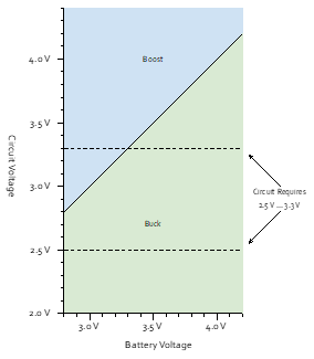
If the performance is most important, you want to use a 3.3 V output buck/boost SMPS. If it is efficiency you are seeking, a 2.5 V buck SMPS is the best and easiest way to go. If you generally
want good performance, but do not mind the performance degrading when the battery gets empty, a buck converter with “Pass-Through Mode” is your best choice. This type of regulator turns on the high side MOSFET for 100% of the time when the input voltage goes below the programmed output voltage.
This example goes to show that the choice for an SMPS topology depends on more than just the electric requirements of the circuit.
Switching Frequency versus Efficiency
The switching frequency of an SMPS determines the general size and efficiency of the solution. Faster switching means smaller capacitors and inductors can be used, but usually is less efficient because of switch drive losses. Faster switching also means that the output voltage can be controlled over a wider frequency range, generally resulting in a faster and better load transient response. However, slower SMPS circuits can be very efficient, even with large input-to-output voltage differences.
If your design requires little quiescent current, there are some fine sub-µA IQ buck converters out there. If your design is required to run cool at high output currents, you might want to look for a lower-frequency controller combined with some beefy external MOSFETs.
General Guidelines
- “Harder, Better, Faster” is a song by Daft Punk, not the way to design your SMPS. Optimize your design for what is required, no more, no less. SMPS solutions can easily become complex, bulky, and expensive.
- Modern buck converter ICs are generally easy and versatile in design. Buck it if you can, boost it if you must.